

MAVwork released for Parrot AR.Drone


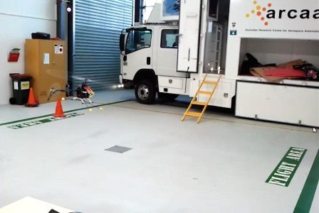
In 2011 I spent the summer in Brisbane, Australia, for a short research stay at the Australian Research Centre for Aerospace Automation (ARCAA). I have very good memories of those days. Not only because of the wonderful natural landscapes of Queensland, but also because of the workplace itself. "How do you dare comparing both? Are you a workaholic?", you might ask. Well, you must understand how awesome it was to arrive there and find an indoor flight area equipped with a brand new underutilized Vicon system. It was like Christmas in summer for a geek willing to make autonomous flying drones. If you prefer to skip all the reading, you can directly watch the results.
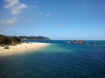
Queensland's natural wonders vs ARCAA's flight area (tough decission)
The problem
The research group in which I worked at that time, the Computer Vision Group, was specialized in the control of unmanned vehicles with Computer Vision techniques. There were multiple multirotor models in the lab and all of them required certain level of experience to be operated safely. My fellow researchers had to spend much time dealing with the hardware at a quite low level and, if you did not have prior experience with it, writing code for autonomous missions was a painful and risky job. The most critical mission stages used to be the take-off and landing and, if something went wrong during a flight, there was no safety mode to keep the drone from crashing. Repairing drones was a usual task.
The AR.Drone from Parrot was already in the market and it had exactly those capabilities, plus a decent frontal camera, at a very affordable price. In addition, it was resilient enough to stand the consequences of buggy control apps. So, why not using the AR.Drone to debug our apps before going to the production environment? But all the other multirotors were different from the AR.Drone so, despite it was a safer method, it would be time-consuming to produce two versions of the app: one for debugging and one for production. Moreover, it would be much better to use directly the debugged code for the production environment, without any modification.
The solution
My proposal to solve all those problems was modifying the drones in the lab to mimic the capabilities of the AR.Drone and writting a middleware so that all of them were interfaced in the same way from the application. That would allow us to run the apps on all the drones with a single version of the code. We would be able to use the AR.Drone for debugging and then moving to the production environment painlessly. The other researchers would only need to learn one API to use all the drones, having more time to focus on their research. And, of course, we would avoid accidents with the safety hover mode and the automation take-off and landing. Altogether, the group would become more efficient and productive.
Once the API was defined and the basic framework architecture was ready, the first natural step was supporting the AR.Drone. This is how MAVwork was born. At the time I am writing these lines, MAVwork supports three different drones.
MAVwork on the AR.Drone
MAVwork communicates control applications with drones through a network. The application interfaces with an API, which is independent from the drone. The API connects with another networked element, named "proxy", which directly speaks to the specific drone hardware and implements the automatic modes. To integrate the AR.Drone in MAVwork, such a proxy was implemented.
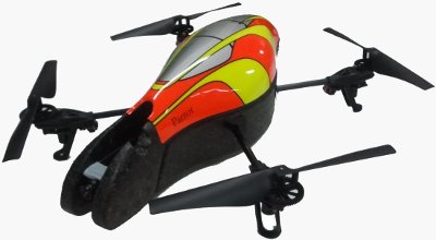
AR.Drone from Parrot was the first drone to be supported by MAVwork
The AR.Drone proxy communicates with the drone thanks to the SDK provided by Parrot. The SDK has C functions to change the drone configuration, to set the flight mode (take-off, land, hover and free flight), to send the desired attitude and altitude rate to the drone and to register callbacks that receive new navigation information and video frames as soon as they are available.
The proxy and the application communicate through an IP network. The communications is logically organized into channels. Each channel transports information with different purposes and requirements. At the low level, channels are implemented with TCP or UDP sockets, depending on their individual needs for safety and latency. In any case, the whole communication is transparent to the application. It only interacts with an object-oriented API that hides the complexity of the underlying processes.
The AR.Drone natively supports the take-off, land and hover automatic modes; therefore, the proxy implementation was much more straight-forward than for the other supported drones. However, as it adds networking, it extends the AR.Drone with new capabilities, like concurrent access of multiple applications to a drone, control of multiple drones from a single application or interaction of multiple apps with multiple drones.
Waypoint controller with Vicon
The first framework version was tested at ARCAA with a simple trajectory controller based on waypoints. The Vicon system, which can be easily accessed from the MAVwork API, was used to sense the AR.Drone's state in real time. For that purpose, reflective markers were attached to the drone's hull. They are the little grey balls in the picture below. The Vicon detects the markers with cameras located around the room, then it is able to determine the position of each marker. Markers can be grouped in the Vicon's user interface to form an object with a user-defined reference frame.
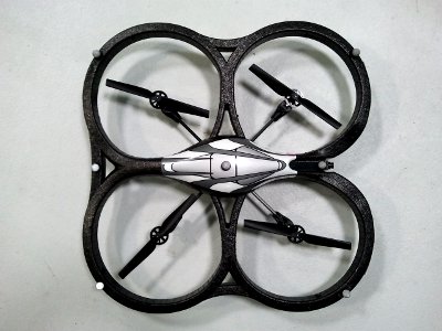
AR.Drone with Vicon markers
The desired trajectory is defined by a sequence of 3D points, named "waypoints", in the inertial frame of the flight area. In every iteration, the next waypoint in the trajectory minus the current position defines a flight vector. Then, four references are obtained:
- Yaw reference = flight vector yaw - drone's current yaw (all magnitudes in the drone local frame; result mapped to [-pi, pi])
- The altitude reference is the altitude of the next waypoint
- The forward speed reference is set by the next waypoint or manually by the user
- The lateral speed reference is always 0, to prevent "drifting" when turning
The trajectory controller was implemented with PIDs, as you can see in the figure below. Desired yaw and altitude are obtained by setting the AR.Drone's yaw and altitude rates. Therefore, P controllers were enough for these two degrees of freedom. As each of them had only one free parameter, they were quickly tuned manually.
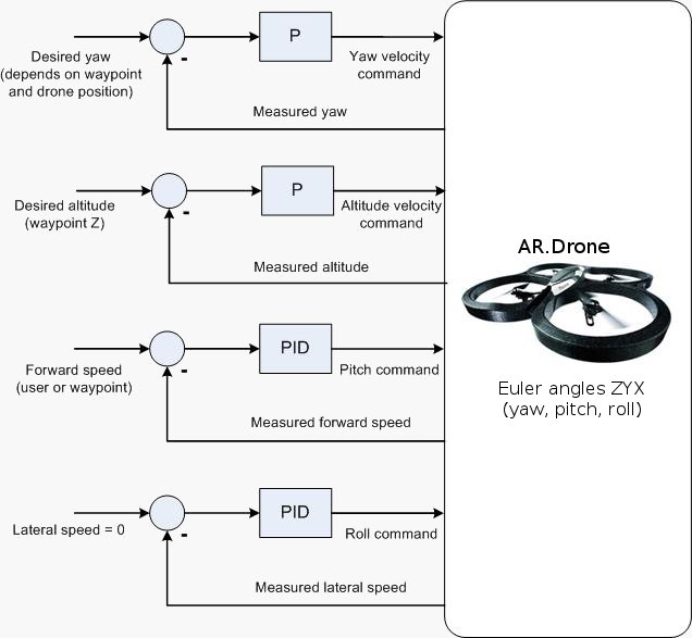
AR.Drone trajectory controller schematic
Forward and lateral velocities, instead, are set by controlling pitch and roll, respectively; each one with a PID. Both PIDs were tuned according to a submodel of the AR.Drone displacement at constant altitude. The model consists of two linear transfer functions: one relates forward velocity to pitch commands, while the other one relates lateral velocity to roll commands. For simplicity, the model assumes that all degrees of freedom are decoupled. The model parameters were found by measuring the velocities with the Vicon after applying pitch and roll command steps. Before applying both steps, the system was taken to a steady state in which it kept moving forward between 0.35 m/s and 0.45 m/s. This speed range was the highest allowed by the diagonal of the Vicon workspace. The system responses to both steps are shown in the figures below.
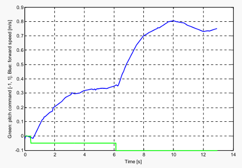
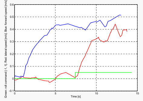
[Left] Forward speed vs pitch command step. [Right] Lateral speed vs roll command step. In both cases, the commands range [-1, 1] is mapped to [-12º, 12º]
Both linear transfer functions are similar and, for simplicity, the PIDs for both pitch and roll were tuned with the same parameters, according to the following approximate rules based on Ziegler-Nichols:
- K = 2 / G = 0.25
- KP = K = 0.25
- KI = K / TI = K / (TS / 3) = 0.25
- KD = 0.01 (manually found after tests with the PI controllers)
Where KP, KI and KD are the PID gains, G is the response gain, TI is the integration time and TS is the settling time.
Initially, I started tuning a PI controller and, once it proved to work well, I added the D component and tuned it with a few manual iterations. This method might not seem very orthodox to purists, but it was quick and the results are good enough, as you can see in the following video, in which the waypoints and forward speed are selected by the user on the fly.
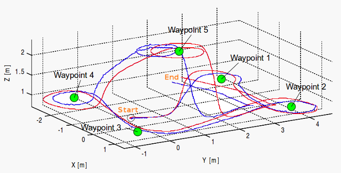
Flight trajectory estimation with odometry (blue) vs Vicon data (red). It corresponds to the first half of the video above.
During the flight, MAVwork logging was enabled and navigation information from both odometry and Vicon was recorded. The flight trajectory was reconstructed from the attitude, altitude and horizontal speed estimation given by the AR.Drone. In the figure above, it is compared with the ground truth given by the Vicon. As expected, the integration of the X and Y velocities accumulates error over time, which produces noticeable position drift after some seconds. These results confirm that the accuracy of the odometry-based position estimation falls down after a short time, making it important for a position-based mission to have an alternative positioning system for the long term, like Vicon, GPS or a Computer Vision method. The latter are among my research interests.
Control apps from other people with MAVwork and AR.Drone
MultirotorController4mavwork by Jesús Pestana:
UAV See and Avoid by Miguel Olivares: